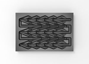
Weave & Zigzag
CNC Virtual Milling
Course: VIS 2225 Digital Media: Design Systems
Instructor: Sawako Kaijima
Collaborator: Candice Wu
Date: Feb.-Mar., 2021
This assignment is to design a 3 axis CNC milling pattern by developing a simple algorithm to describe a tool path over the grid(s). In this document, “physical” refers to virtual milling that is analogous to physical milling. The target should rely on two things: the tool path and the material layout of the block to be milled.
KEYWORDS:
CNC Milling, Tool Path, Material Layout
OBJECTIVES
1. The tool path needs to be a single polyline.
2. The milling bed is 2 meters by 1 meter. (the base file is in centimetres)
3. The tool head is a spherical mill head where students can specify the
radius. (select one radius for the entire tool path)
4. The block needs to be a Cuboid and should fit within the milling bed.
5. The milling path should not create any undercuts (in case you plan to move
the milling path along the z-axis)
6. The maximum time for milling is limited to 1000 min which is calculated by
the total length in centimetres * 1 min + the number of turns it takes*3 min.
Precedent
Tessellation Pattern

The phenomena of “tessellation” can be observed in nature and our daily life. For instance, the pineapple has a skin that is tessellated with the shape of polygon units. Inspired by this precedent, we explored the virtual milling by tessellation logic.
Methodology
3 Axis CNC Milling

Experiment
Algorithm in GH C#

Geometric Logic
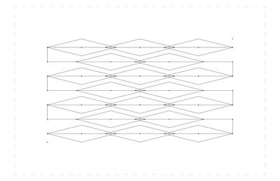
The aim is to create a tessellation pattern of rx columns and ry rows of diamonds. The diamonds are defined by a centroid and two parameters of diagonal length (la & lb). Since the centroid’s location are determined by the two bounding points and row/column counts, it is independent of la & lb, which gives the opportunities for diamonds to overlap and create sub-patterns.

Grid Construction
The grid is constructed in quads, starting with a reference point determined by the distance between centroid and the index of points. The four-point set is constructed in sequence by simply adding calculated distance to the previous point. The rows are constructed in alternating directions for a smooth transition.
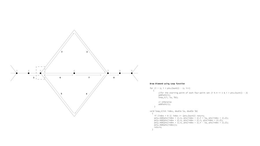
Path Generation
The path of the diamond consists of two parts. First a loop function that generates a diamond shape at every fourth point. The diamond top and bottom corner both refer to the centroid for location, which makes the code more efficient as it needs less points. When the index numbers are not the point for a diamond, every point is added to create a continuous path.
Experiment
Line-based Prototype


Experiment
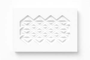
Drill Head Size Test

Dill Head Size Variations
X count (rx) = 3
Y count (ry) = 7
X Length (lb) = 4.00
Y Length (la) = 3.10


Dill Head Size Variations
X count (rx) = 3
Y count (ry) = 7
X Length (lb) = 5.28
Y Length (la) = 1.31

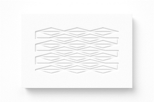
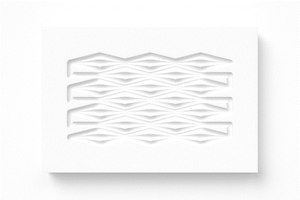

Dill Head Size Variations
X count (rx) = 8
Y count (ry) = 3
X Length (lb) = 1.44
Y Length (la) = 5.80


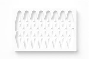
Experiment
Z-axis Tilt Variation
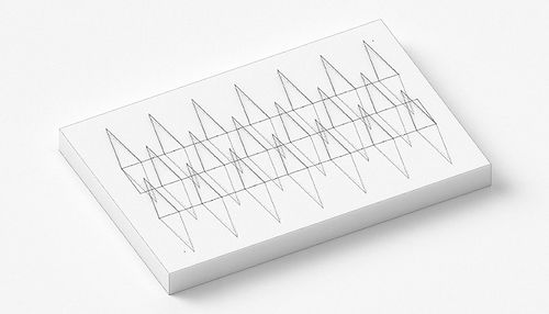

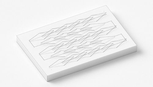

Experiment
Prototype Rendering


Material Dimensions: 26x38.6 cm
Drill Raduis: 0.55 cm
Z-axis: h=0.5 cm
Time Cost: 909 min
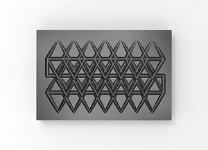

Material Dimensions: 26x38.6 cm
Drill Raduis: 0.60 cm
Z-axis: h=0.5 cm
Time Cost: 1045 min

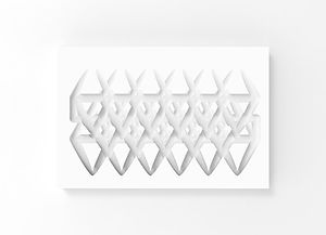
Material Dimensions: 26x38.6 cm
Drill Raduis: 0.80 cm
Z-axis: h=0.8 cm
Time Cost: 974 min


Material Dimensions: 26x38.6 cm
Drill Raduis: 0.60 cm
Z-axis: h=0.6 cm
Time Cost: 1375 min


Material Dimensions: 26x38.6 cm
Drill Raduis: 0.80 cm
Z-axis: h=0.8 cm
Time Cost: 1379 min
